一、升级H3C到最新版本,重启多次检测设备是否正常,主备切换测试
二、设备的虚拟化配置
拓扑图如下
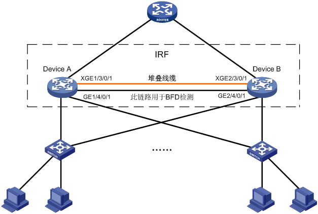
采用BFD MAD检测方式
配置步骤:
(1) 7506 A和7506 B不连堆叠线,分别上电,分别配置
# 配置Device A的成员编号为1,创建IRF端口2,并将它与物理端口Ten-GigabitEthernet8/0/1,Ten-GigabitEthernet8/0/2绑定。
<Sysname> system-view
[Sysname] irf member 1 //配置成员编号
[Sysname] irf priority 10 //配置该设备的优先级
[Sysname] irf-port 2 //创建IRF端口
[Sysname-irf-port2] port group interface ten-gigabitethernet 8/0/1 //将IRF端口与物理端口绑定
[Sysname-irf-port2] port group interface ten-gigabitethernet 8/0/2
[Sysname-irf-port2] quit
# 将当前配置保存到下次启动配置文件。
[Sysname] quit
<Sysname> save
# 将设备的运行模式切换到IRF模式。
<Sysname> system-view
[Sysname] chassis convert mode irf
The device will switch to IRF mode and reboot. You are recommended to save the current running configuration and specify the configuration file for the next startup. Continue? [Y/N]:y
Do you want to convert the content of the next startup configuration file flash:/startup.cfg to make it available in IRF mode? [Y/N]:y
Please wait...
(2) 配置Device B
# 配置Device B的成员编号为2,创建IRF端口1,并将它与物理端口Ten-GigabitEthernet8/0/1,Ten-GigabitEthernet8/0/2绑定。
<Sysname> system-view
[Sysname] irf member 2
Info: Member ID change will take effect after the switch reboots and operates in IRF mode.
[Sysname] irf-port 1
[Sysname-irf-port1] port group interface ten-gigabitethernet 8/0/1
[Sysname-irf-port1] port group interface ten-gigabitethernet 8/0/2
[Sysname-irf-port1] quit
# 将当前配置保存到下次启动配置文件。
[Sysname] quit
<Sysname> save
#将两台设备IRF接口连接好堆叠线缆。
# 将设备的运行模式切换到IRF模式。
<Sysname> system-view
[Sysname] chassis convert mode irf
The device will switch to IRF mode and reboot. You are recommended to save the current running configuration and specify the configuration file for the next startup. Continue? [Y/N]:y
Do you want to convert the content of the next startup configuration file flash:/startup.cfg to make it available in IRF mode? [Y/N]:y
Please wait...
(3)配置BFD MAD检测
# 创建一个动态聚合接口,并使能BFD MAD检测功能。
<Sysname> system-view
# 创建VLAN 999,并将Device A(成员编号为1)上的端口1/2/0/12和Device B(成员编号为2)上的端口2/2/0/12加入VLAN中。
<DeviceA> system-view
[DeviceA] vlan 999
[DeviceA-vlan999] port gigabitethernet 1/2/0/12 gigabitethernet 2/2/0/12
[DeviceA-vlan999] quit
# 创建VLAN接口999,并配置MAD IP地址。
[DeviceA] interface vlan-interface 999
[DeviceA-Vlan-interface999] mad bfd enable
[DeviceA-Vlan-interface999] mad ip address 172.16.255.253 255.255.255.0 member 1
[DeviceA-Vlan-interface999] mad ip address 172.16.255.254 255.255.255.0 member 2
[DeviceA-Vlan-interface999] quit
# 因为BFD MAD和MSTP功能互斥,所以在GigabitEthernet1/2/0/12和GigabitEthernet2/2/0/12上关闭MSTP协议。
[DeviceA] interface gigabitethernet 1/2/0/12
[DeviceA-gigabitethernet-1/2/0/12] undo stp enable
[DeviceA-gigabitethernet-1/2/0/12] quit
[DeviceA] interface gigabitethernet 2/2/0/12
[DeviceA-gigabitethernet-2/2/0/12] undo stp enable
[DeviceA-gigabitethernet-2/2/0/12] quit
交换机虚拟化配置完成。
本文出自 “Steven Home” 博客。